top of page


Low-Profile Connector Assembly Instructions
Installing our Low-Profile connectors is quick & easy and below are some tips to get you on your way to "DIY" custom cable making. Specific instructions for XLR, 1/4" and TA are clearly noted. Since you're making your own cables we'll assume you know how to tin the connector cups and prep the cable leads so we will not include these basic solder techniques in our instructions.

What's in the Package:
- M or F Connector Shell
- Insert [3-pin 4-Pin or 5-pin]
- Color Cap
- (2) Grub Screws, 1.5mm Hex Head
- Mini Zip-Tie

What's in the Package:
- Connector Shell
- Plug Insert [2-Pole or 3-Pole]
- Color Cap
- (2) Grub Screws (1.5mm Hex Head)
- Mini Zip-Tie


What's in the Package:
- LPS Connector Shell
- Insert, 3-pin, 4-pin or 5-pin
- Color Cap
- Insulator
- (2) Grub Screws, 0.9mm Hex Head

What's in the Package:
- Black housing, 2 sides
- 2 Banana pins
- End cap
- Cable Clamp
- Screw and Nut
Besides the 1.5mm Hex wrench you do not need any special tools beyond what is standard to install classic straight XLR connectors. Method is the same for Male or Female, 3-pin, 4-pin or 5-pin connectors.


1. Remove approximately 12-15mm of the cable jacket. Fray and twist the shield tight and TIN ONLY about 4mm at the end.


2. Put flexible 2:1 heat shrink over the non-tinned shield leaving the 4mm tip exposed. Tin the + & - leads. Put a 5mm cut of 2:1 heat shrink on the wire before you solder the leads to the insert. This will soon be heated over the area where the leads exit the jacket for insulation and strength of the joint. Solder the leads into the insert solder cups. Heat the shrink over the joint. Install the included mini Zip-tie strain relief at the edge of the insulation shrink as shown. The "head" of the Zip-tie should be positioned to the side - pull it nice and tight.


3. Place the insert into the XLR shell and bend the cable towards the position you would like the cable to exit the cap. Install the color cap. Carefully pull the cable so the Zip-tie rests against the inside of the cap exit. Install the Grub screws with a 1.5mm Hex wrench while applying constant pressure to hold the cap in place. DO NOT OVERTIGHTEN! You only need to torque the screws to the point where the screw is flush with the outer shell. Overtightening can damage the color cap.


4. You can loosen the Grub screws and carefully twist the cap between the screws to align the cable exit to your preference. If you need the exit to be on the opposite side of the connector, e.g. Exit off of PIN 2 instead of PIN 1, you will need to remove the cap and bend the cable assembly carefully towards the other side. If you just remove the screws and twist the cap all the way around to the other side you will have a bad day.

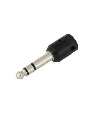
Besides the 1.5mm Hex wrench you do not need any special tools beyond what is typical to solder standard 1/4" plugs. Method is the same for 2-Pole and 3-Pole other than the extra solder connection.


Step 1. Strip cable jacket back ½” (half-inch).
Step 2: Strip & Tin conductors (Solder Tip only - about 3mm tinned). *Most importantly on the shield so it remains flexible to easily bend for positioning when installing shell and cap.


Step 3: Use small cut of 3/64” 2:1 polyofelin shrink on the twisted shield with tinned end left exposed.
Step 4: Pre-tin connector lugs (*INSIDE surface of solder tab).


Step 5: Solder each wire lead to the “inside” of the appropriate connector lugs.
Step 6: Install Mini Zip-tie over the shrink tube/cable jacket about 2 mm from the edge. If the ground tab
is at 12 o’clock the Zip-tie head should face 6 o’clock Use a needle-nose to pull it tight and snip off tail. *Zip-tie installation is an additional level of strain relief that is not always necessary e.g. shortie Pedalboard jumpers with Mogami W2314 can do without it as the cap compression alone is maximized.
If you are using a cable with an overall diameter less than the cap outlet use an appropriate sized polyolefin shrink cut to about 17mm to "build up" cable to be compressed by Cap outlet.


Step 7: Carefully bend the cable to 90º of the plug directly opposite of the shield tab as shown. After bending the Zip-tie head should be facing down over the round insulator as shown.


Step 8: Insert soldered phone plug into the metal housing shell. Note that the plug insert and shell are “keyed” with a tongue & groove so it only fits one way. The key secures the plug and prevents spinning movement and also makes it super simple to handle to put together.


Step 9: The Color Cap is “keyed” as well. Line up cap and press into place all the way down. The cable will be tight to get over at first try which is what you want to compress the cable. The Zip-tie head goes in just inside of the metal shell.
Step 10: While tightly holding cap and housing together tighten the set screws flush with shell *DO NOT OVERTIGHTEN screws. Set screws should be flush just enough that you don’t feel the screw edge when you run your finger over the screw area while in place.


1. Remove approximately 6mm of the cable jacket. Fray and twist the shield tight and tin all leads.
Note: the ideal cable OD for LPS connectors is about 2.7mm to 3.0mm. Belden 1804A is about 2.9mm.


2. Put a 5mm cut of 1/8" 2:1 polyolefin heat shrink and the insulator on the wire before you solder the leads to the insert - Adhesive shrink is even better! Solder the leads into the insert solder cups. "Milk" the recessed cable jacket up if needed. Note: if you use a cable diameter about 2.6mm or less you should use a 15mm cut of shrink so it goes through and out the color cap outlet for maximum stability.


3. Push the the shrink over the joint as far as it can go. It should stop at the edge of the solder cups. Heat it carefully. Place the insulator into position. If the leads and shrink are the ideal length you'll see the shrink poke out a little from the back of the insulator as shown.


4. Remove the grub screws from the baggy and place on the hex wrench. Install the screws with just a few turns so they stop flush with the inside of the shell. We recommend getting a nice .9mm Hex driver like a Wiha brand driver if you build many cables as the tiny Hex wrenches seem to fail and strip quite easy.


5. Place the completed insert into the shell and slide the color cap over the cable on either side or screws based on the gear panel it will be plugged into. *Make sure the insert is seated all the way in or the cap will be impeded and won't sit correctly.


6. Squeeze the cap so it is flush with the shell opening so the inside cap channel will line up properly. While squeezing screw down the grub screws maybe a couple turns. You can now adjust the exact angle between the screws. Once aligned tighten the grub screws so they are flush with the shell - no more. Do Not over-tighten!
Note: Never try to twist the cap through the grub screws or the leads will be severed. Always remove the cap and place it to the other side e.g. Left or right exit.


7. LPS TA connectors allow for the ideal angle to be set for gear panels so the cable doesn't mash up against the connector beside it. The above photo on the left is the angle for Sound Devices 6-Series. On the contrary, a cap installed for the Lectrosonics SR bottom would exit on the other side of the release pin.

8. The final result. Life is good.


LPS TA
XLR
DTAP
1/4"
bottom of page